
 English
 Español
 Português
 Русский
 العربية
 Français
 Deutsch
 中文
 日本語
 한국어
Moulding a Tubular Housing with Mounting Features
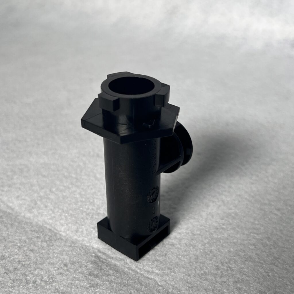
This sample combines a hollow cylindrical body with a mounting flange and lateral features. Such geometry illustrates the decisions involved in designing a mould for a compact housing that must fit into an assembly.
Define the assembly interfaces
The drawing should distinguish the bore, flange, base and any side features that locate or retain the part. Their relationship to the assembly datums, allowed distortion and the relevant mating components should be agreed before tooling begins. The sample photograph does not establish its resin, tolerance or customer application.
Review the moulding direction
The mould design must accommodate the hollow core and determine how each lateral feature can be formed and released. Depending on the approved geometry, side actions or other arrangements may be considered. The team can review wall transitions, draft, filling, cooling and ejection positions together so the proposed tool supports the specified fit and appearance.
Plan useful sample checks
Trial review can cover bore and mounting dimensions, completeness of local features, flange flatness and fit with the specified mating part. Appearance requirements, inspection methods and any functional checks should be agreed for the actual drawing. Production material and process records help preserve the agreed basis for later orders.
Start a similar project
Share the part model and drawing, material and service conditions, sample quantity and expected production demand. Read how to request a tooling quotation or contact yw07@jz-mould.com.
Let’s Build Precision Moulds Together
Upload your CAD files or share your product specifications. Our engineering team will respond with a detailed quotation within 24 hours.