Case Studies

Explore JingZhan tooling and component examples, from optical lens moulds and laboratory containers to mirror-finished cavities and automotive lighting parts.

ToolingMouldingSurface finishingComponent review

From product geometry to a practical process plan

Each example highlights the features that matter in manufacturing, the questions to resolve before tooling and the checks to agree before production. Select a field below or open the case notes for a closer look.

Optical & lighting

Optical surfaces and light management

2 examples
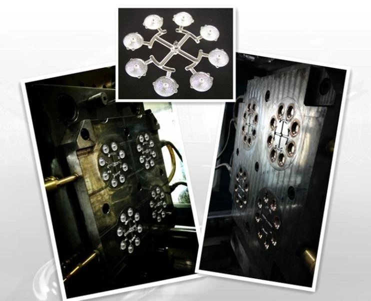
Optical lens tooling and a connected set of moulded lens samples from the JingZhan portfolio
CASE 01Optical & lighting

Multi-Cavity Optical Lens Tooling

Lens tooling brings optical surfaces, cavity layout and moulded-part consistency into the same review.

Engineering focus
Optical surface condition, cavity-to-cavity consistency and gate location.
Process route
Precision toolmaking, surface finishing and injection-moulding trials.
Verification
Lens profile, visible defects and application-specific optical checks agreed before sampling.
Read case notes

The portfolio pairs a lens runner layout with its tooling. A practical review starts with the optical design, resin grade and the surfaces that must remain clear. Gate vestige, release marks and handling protection need to be considered alongside the lens geometry. Trial samples should be evaluated against agreed dimensional, visual and optical criteria; appearance alone does not establish optical performance.

For your enquiry
Lens drawing or optical model, resin grade, cosmetic zones and the required optical acceptance method.
Explore Optical Products
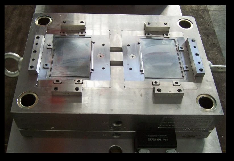
Rectangular light-guide plate mould with two cavity areas in the JingZhan company portfolio
CASE 02Optical & lighting

Light-Guide Plate Moulds

Broad, thin optical parts require the cavity surface and the moulded plate to be considered together.

Engineering focus
Surface replication, plate geometry, flatness and protected viewing areas.
Process route
Cavity machining, specified surface preparation and moulding trials.
Verification
Plate dimensions, warpage and the agreed illumination or visual assessment.
Read case notes

The example shows the mould construction used for a light-guide plate application. For a new project, the illuminated area, thickness transitions and intended light-source arrangement guide the tooling review. Surface requirements should be defined clearly rather than described only as "high gloss". Sample approval can combine dimensional checks with a lighting test that represents the intended assembly.

For your enquiry
Plate outline and thickness, light-source arrangement, material and viewing-surface requirements.

Explore Optical Products

Medical & laboratory

Containers and repeated well geometries

2 examples
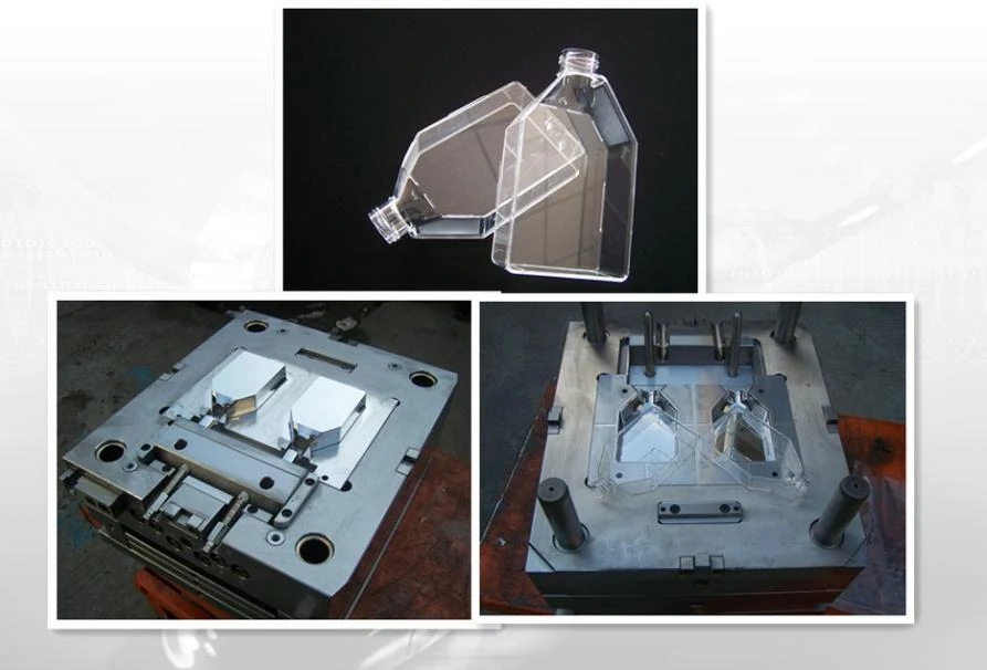
Clear laboratory culture container and corresponding mould photographs from the JingZhan portfolio
CASE 03Medical & laboratory

Laboratory Culture Containers

Clear container bodies connect mould geometry with the opening, mating features and intended laboratory workflow.

Engineering focus
Body geometry, neck and closure interfaces, clarity and release features.
Process route
Mould development, transparent-part moulding and sample review.
Verification
Dimensions, appearance and the fit or integrity tests specified for the complete assembly.
Read case notes

The supplied portfolio presents a culture-container sample together with its mould. The neck, broad body faces and local transitions create different tooling and inspection priorities. A project review should distinguish a dimensional requirement from an assembly or sealing requirement. Resin documentation, handling cleanliness and any sterilisation-related requirements must be specified for the actual application.

For your enquiry
Container and closure drawings, intended use, resin and documentation requirements, and the agreed assembly checks.

Explore Medical Products
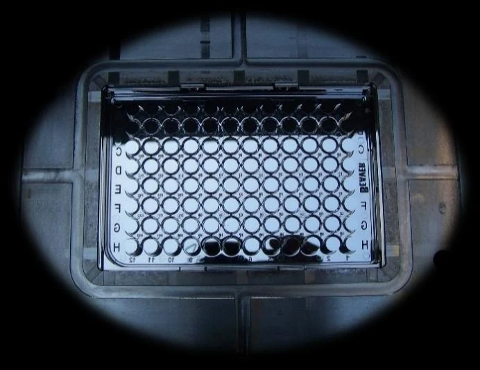
Repeated well geometry visible in a culture tray tooling photograph from JingZhan
CASE 04Medical & laboratory

Multiwell Culture Tray Tooling

A repeated well pattern makes local geometry and consistency across the full tray equally important.

Engineering focus
Well layout, repeated geometry, tray flatness and lid or holder interfaces.
Process route
Precision mould manufacture, moulding trials and pattern-based inspection.
Verification
Well positions and dimensions, flatness, visible defects and fit to the specified mating component.
Read case notes

The repeated well layout shown in the portfolio is useful for discussing how a tray will be measured and approved. A review should define which wells and datums establish the inspection plan, how the tray sits in its holder and which surfaces affect the laboratory workflow. Sampling across the pattern helps make local variation visible before a repeat-production basis is agreed.

For your enquiry
Well layout, critical dimensions, holder or lid interface and the required inspection coverage.

Explore Tray & Lens Components

Precision tooling & finishing

Working surfaces and enclosure interfaces

2 examples
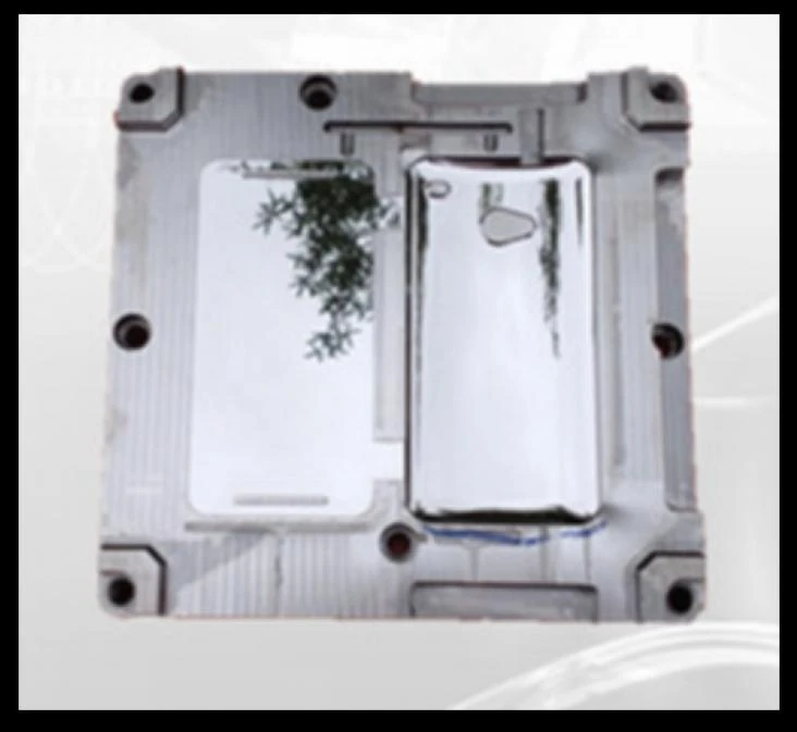
Reflective mould cavity surfaces illustrated in the JingZhan mirror-polishing portfolio
CASE 05Precision tooling & finishing

Mirror-Finished Mould Cavities

Mirror polishing is planned around the working geometry and the surface that will transfer to the moulded part.

Engineering focus
Cosmetic surfaces, edge definition, local features and the specified finish zones.
Process route
Component machining followed by the finishing and polishing operations required by the drawing.
Verification
Surface appearance and geometry against the agreed finish specification and acceptance method.
Read case notes

The company profile identifies complete component machining and mirror polishing as part of its portfolio. The reflected scene in this photograph illustrates surface appearance; it is not a numerical roughness measurement. For production tooling, finish zones, sharp-edge restrictions, polishing access and protective handling should be defined together so the finishing work supports the intended part geometry.

For your enquiry
Tool drawings, finish zones, surface standard or reference sample, and any edge or texture restrictions.

Explore Mould Development
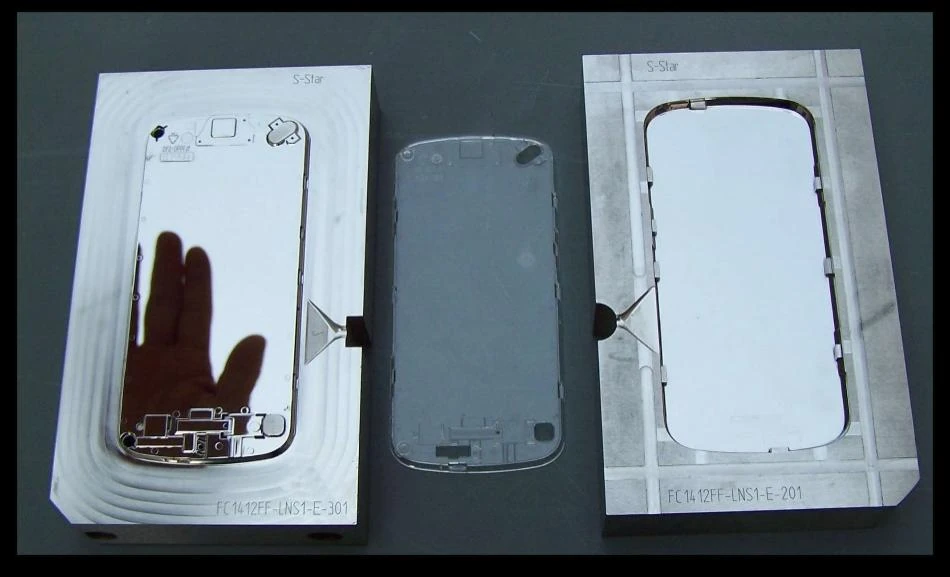
Electronic enclosure sample between two precision mould inserts in JingZhan portfolio photographs
CASE 06Precision tooling & finishing

Tooling for Electronic Enclosures

An enclosure combines a visible outer face with detailed openings and internal assembly features.

Engineering focus
External appearance, local openings, mating edges and internal locating features.
Process route
Tool component machining, appropriate surface finishing, mould assembly and trial sampling.
Verification
Defined datums and dimensions, mating-part fit and the approved cosmetic zones.
Read case notes

The tooling and enclosure views show why cosmetic and functional features need one shared review. A thin wall, opening or locating feature may influence the tool split and the way the part is released. The drawing revision, mating components and finish references should therefore be available before the tooling route is confirmed. Trial review then connects measured features with actual assembly fit.

For your enquiry
2D/3D part files, mating components, cosmetic references and the expected production quantity.

Explore Electronics Products

Automotive & components

Curved cavities and formed components

2 examples
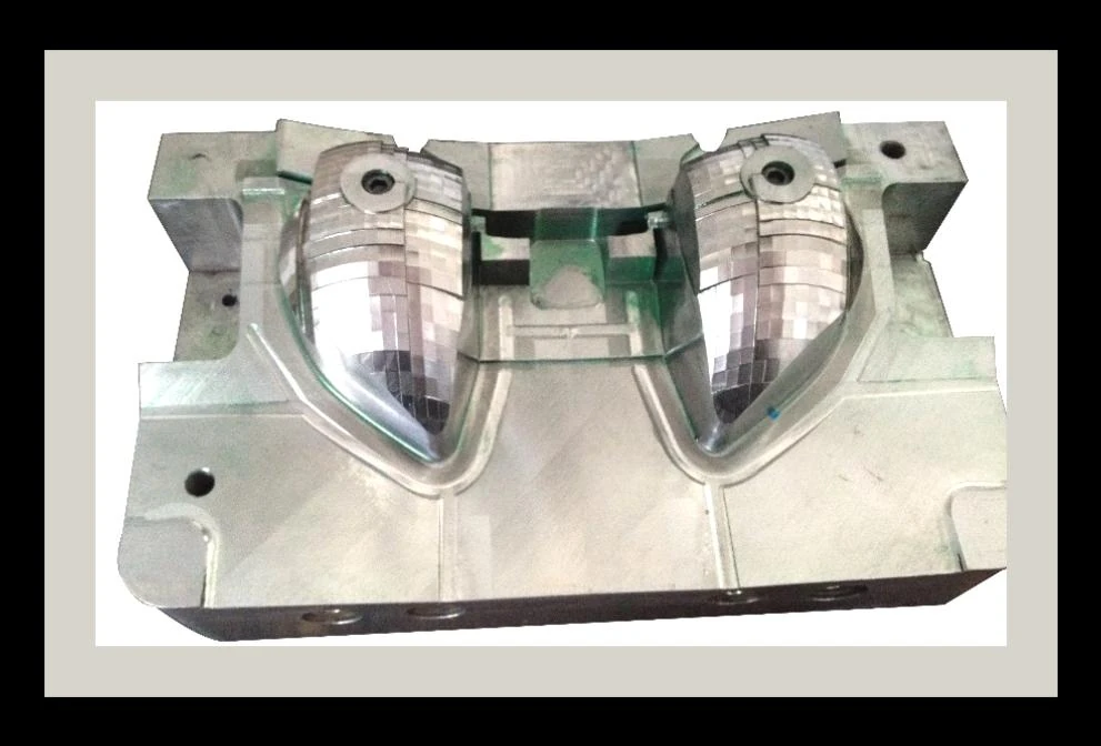
Paired curved automotive lighting mould cavity inserts from the JingZhan portfolio
CASE 07Automotive & components

Automotive Lighting Mould Cavities

Curved lighting components bring optical or cosmetic faces together with the features needed for assembly.

Engineering focus
Curved working surfaces, mounting interfaces, release direction and surface protection.
Process route
Precision cavity machining, specified finishing and trial review with the part design.
Verification
Profile and mounting dimensions, visible marks and the lighting or assembly checks required by the project.
Read case notes

The company portfolio includes vehicle-light tooling and sample components. For a new lamp project, the tool review should connect the curved surfaces with mounting features and the intended assembly. The acceptance basis needs to distinguish surface appearance, component fit and any functional lighting requirement. Changes to material or geometry should be reviewed before a production basis is released.

For your enquiry
Part and assembly drawings, material, critical optical or cosmetic zones and the agreed functional tests.

Explore Automotive Products
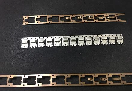
Strip-form stamped metal component samples illustrated in the JingZhan company profile
CASE 08Automotive & components

Stamped Precision Components

Strip-form samples make repeated profiles, openings and formed features visible in a compact component layout.

Engineering focus
Repeated pitch, feature position, formed details and edge condition.
Process route
A drawing-led review of the component, material and tooling requirements.
Verification
Profile, hole position, formed geometry and any burr or edge requirements defined for the part.
Read case notes

Stamped samples appear in the company profile alongside the moulding and tooling examples. They provide a starting point for a component discussion rather than a fixed material or capacity specification. A new enquiry should define sheet grade and thickness, feature geometry and the required edge condition. The applicable process scope and supply arrangement can then be confirmed against the drawing.

For your enquiry
Part drawing, sheet grade and thickness, edge requirements and expected order quantity.

Discuss This Component

Bring us your part requirements

Share drawings, material, finish requirements and expected quantities. We can review the tooling route, sample checks and repeat-order requirements with your team.

E-mail Whatsapp