
 English
 Español
 Português
 Русский
 العربية
 Français
 Deutsch
 中文
中文 日本語
日本語 한국어
한국어Transparent Device Housings Built Around Assembly Requirements
Sample-Based Manufacturing Review
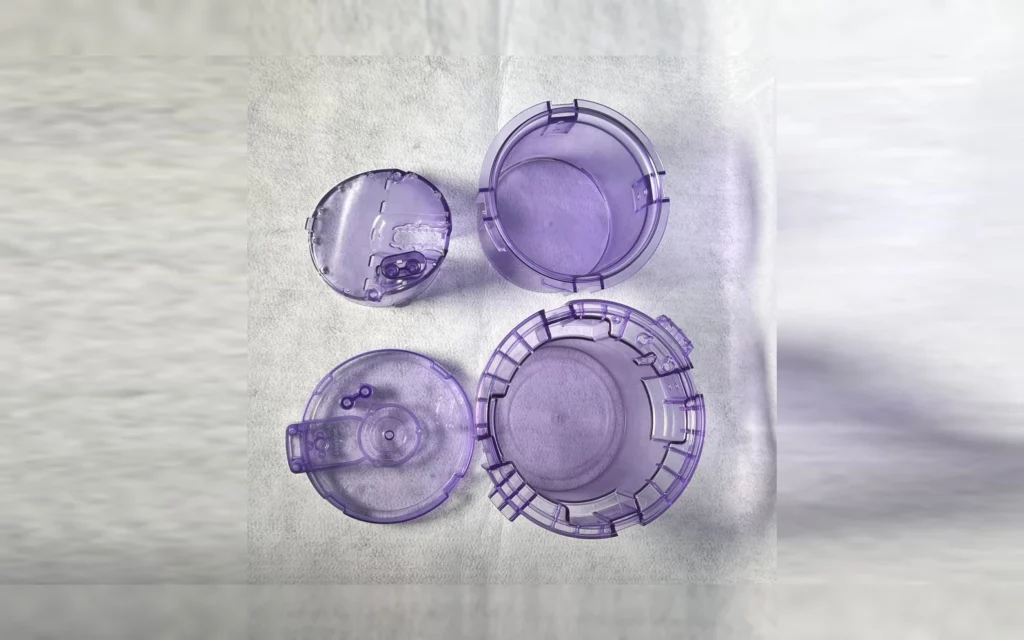
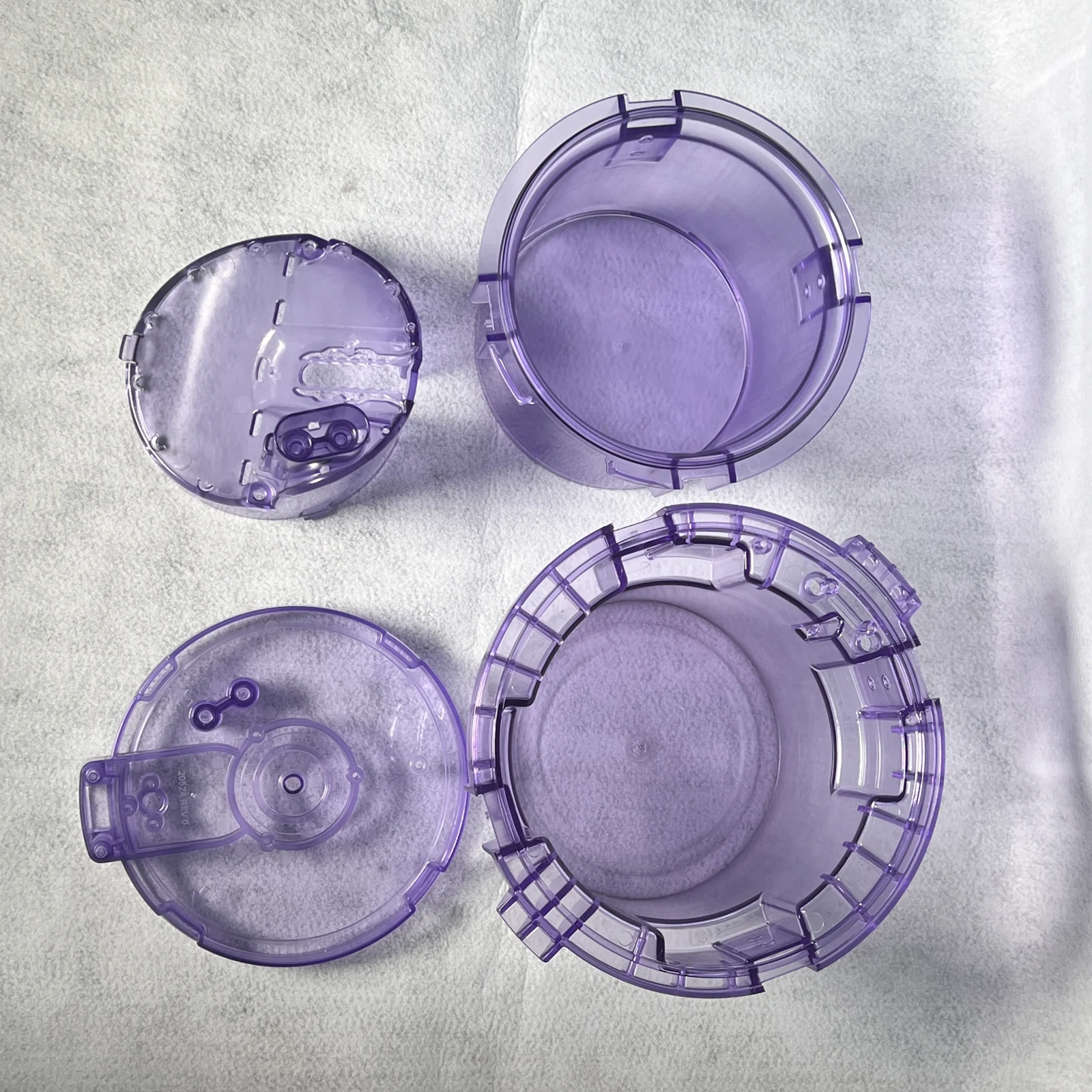
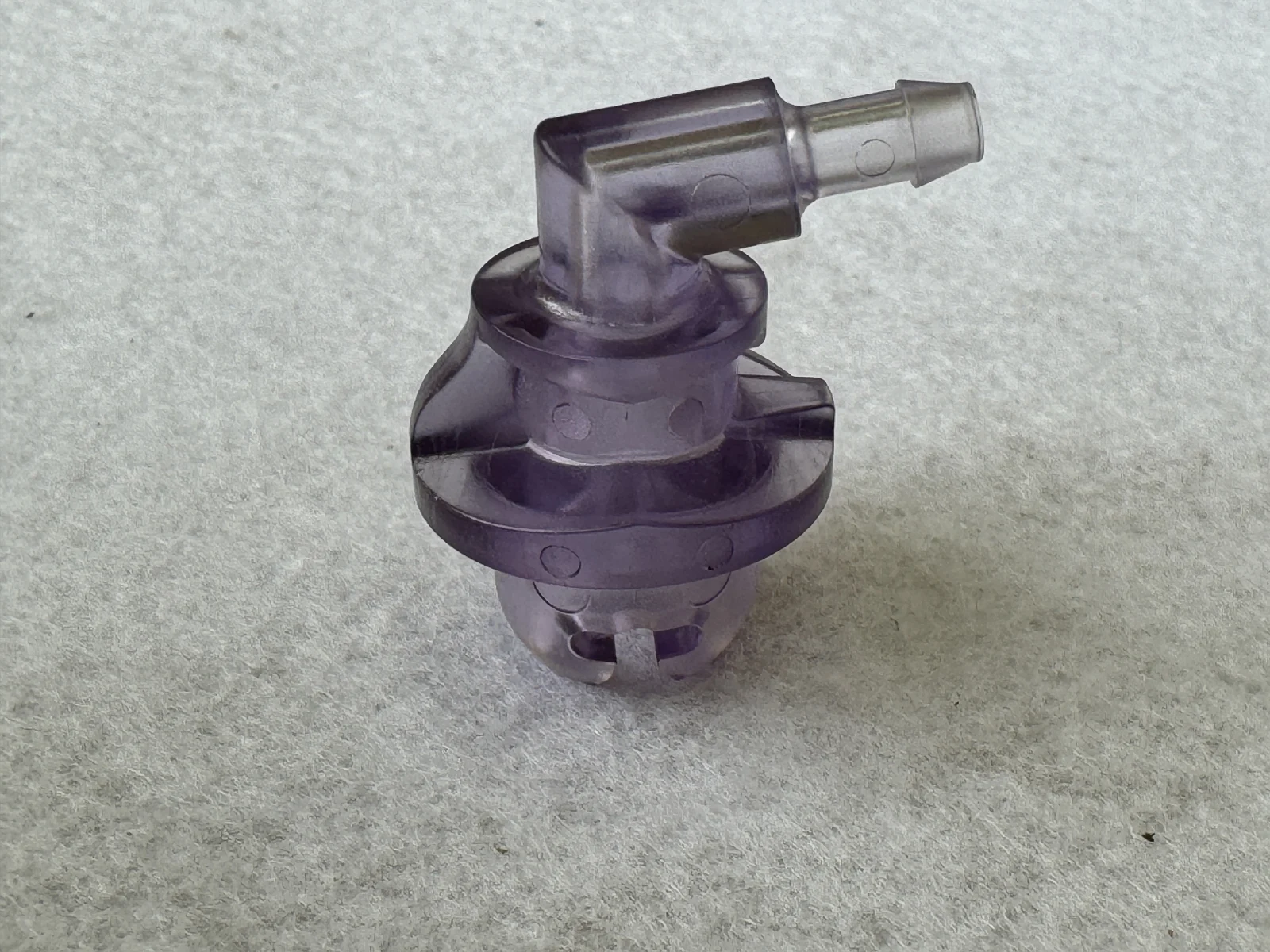
Transparent housings bring the outside surface and the internal structure into the same field of view. The purple-tinted samples in JingZhan’s photo archive include enclosure halves, circular rims, projecting interfaces and small connecting components. They offer a useful starting point for discussing how appearance and assembly requirements should be defined together.
Start with the enclosure interface
The grouped samples show more than a smooth outer shell. Their rims, tabs and adjoining pieces create a series of interfaces that must be reviewed against the mating assembly. A practical drawing should identify which edge locates the part, which surfaces remain visible and where contact with another component is intended.
A visually similar housing is not automatically interchangeable. The flange profile, local clearance and engagement of a latch or fastener need their own acceptance criteria. For a new project, the engineering review should separate functional dimensions from purely cosmetic areas before tooling work begins.
Keep appearance criteria specific
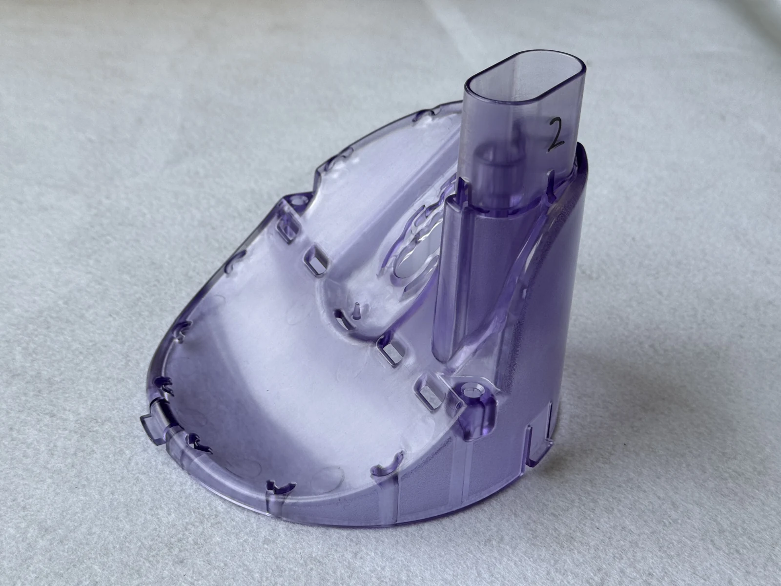
Tinted transparency can help reveal internal components, but a photograph does not establish optical transmission, haze or resin grade. Buyers should provide an approved colour sample, identify viewing areas and state whether flow marks, gate vestiges or ejector marks are acceptable in those locations.
Mould surface condition and handling deserve attention alongside the part design. A review can consider how the visible face will be supported during ejection, where parts may touch one another in packing and whether assembly operations could introduce scratches. These are project planning points, not performance results inferred from the photos.
Review the housing and its neighbouring parts together
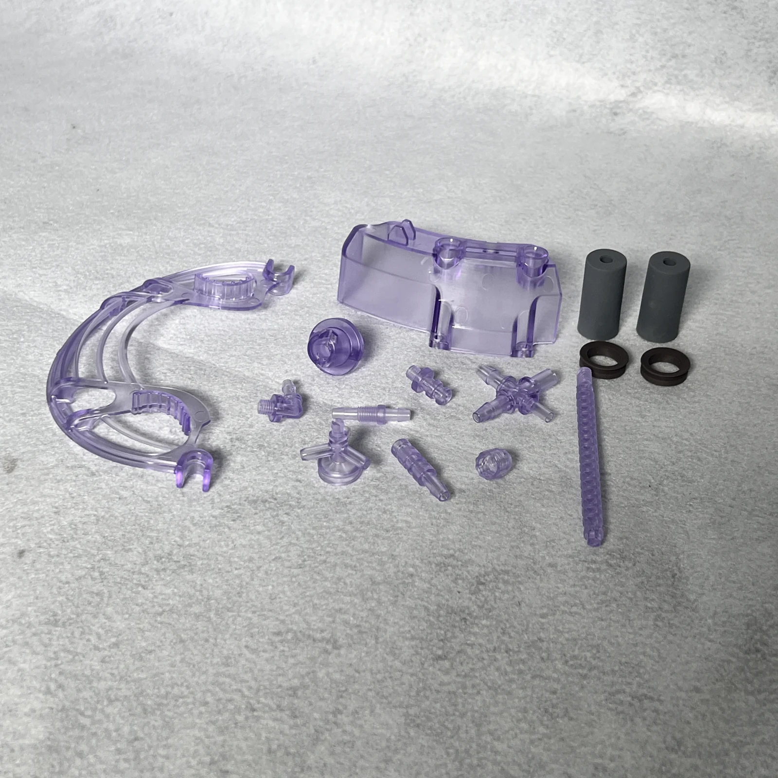
The other samples show how curved shells can sit beside small fittings and formed interfaces. Reviewing these pieces as an assembly helps avoid approving the enclosure in isolation while overlooking access, orientation or the order in which components must be fitted.
Where a housing is intended for diagnostic or medical equipment, the specified material, cleaning exposure and applicable documentation must be agreed for that application. Transparency alone does not establish suitability for medical use or compatibility with a sterilisation method.
Suggested sample approval checks
| Review area | What to agree before production |
|---|---|
| Mating rim | Check profile and clearance against the approved counterpart. |
| Visible surfaces | Agree colour and cosmetic limits using a reference sample. |
| Local interfaces | Review orientation, access and assembly sequence. |
| Packing | Protect viewing areas and prevent part-to-part scratching. |
Planning a comparable part
For quotation, send the housing and mating-part drawings, the intended material grade, colour reference, visible-surface map and expected order volume. Sample approval should cover both appearance and the assembled fit rather than either item alone.
Explore related moulded components →
Technical background: Manufacturer and moulding-design guidance. General guidance is not a test report for the photographed samples.
Discuss your part and assembly requirements
Share your 2D/3D drawings, material requirements and expected production volume for a project review.
Let’s Build Precision Moulds Together
Upload your CAD files or share your product specifications. Our engineering team will respond with a detailed quotation within 24 hours.