
 English
 Español
 Português
 Русский
 العربية
 Français
 Deutsch
 中文
中文 日本語
日本語 한국어
한국어Long Electronic Housings That Balance Stiffness and Fit
Sample-Based Manufacturing Review
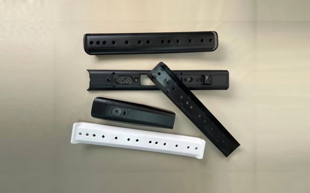
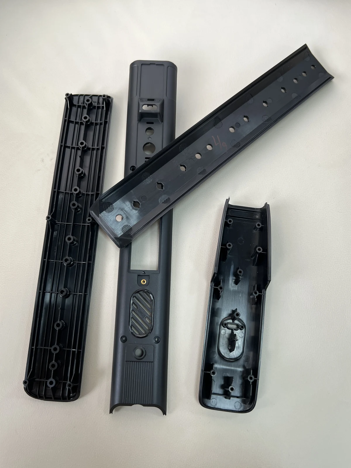
Long plastic housings often combine a simple outer profile with a surprisingly detailed interior. The samples shown here include narrow rails, elongated covers, repeated holes and local reinforcement features. Looking at the complete length and the small attachment details together is more useful than treating the part as an ordinary rectangular moulding.
Use assembly datums to define straightness
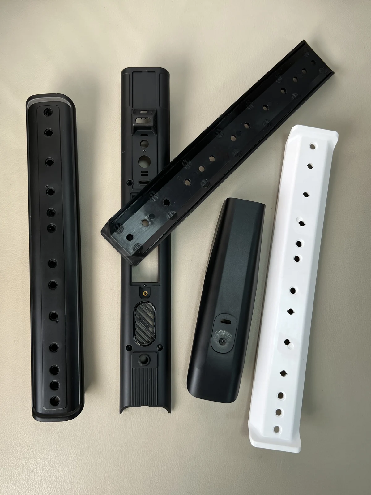
The group photograph makes the difference between a long cover, a supporting rail and a more complex frame easy to see. Each part needs a defined reference for inspection. A free-state straightness check may answer a different question from a check made with the part clipped or screwed into its actual assembly.
The drawing should identify mounting points, clearance-sensitive edges and the permitted relationship between holes along the length. A single overall length dimension cannot describe all of these conditions. Where the part is flexible, the inspection support and measuring method should also be agreed.
Review local sections as well as the overall profile
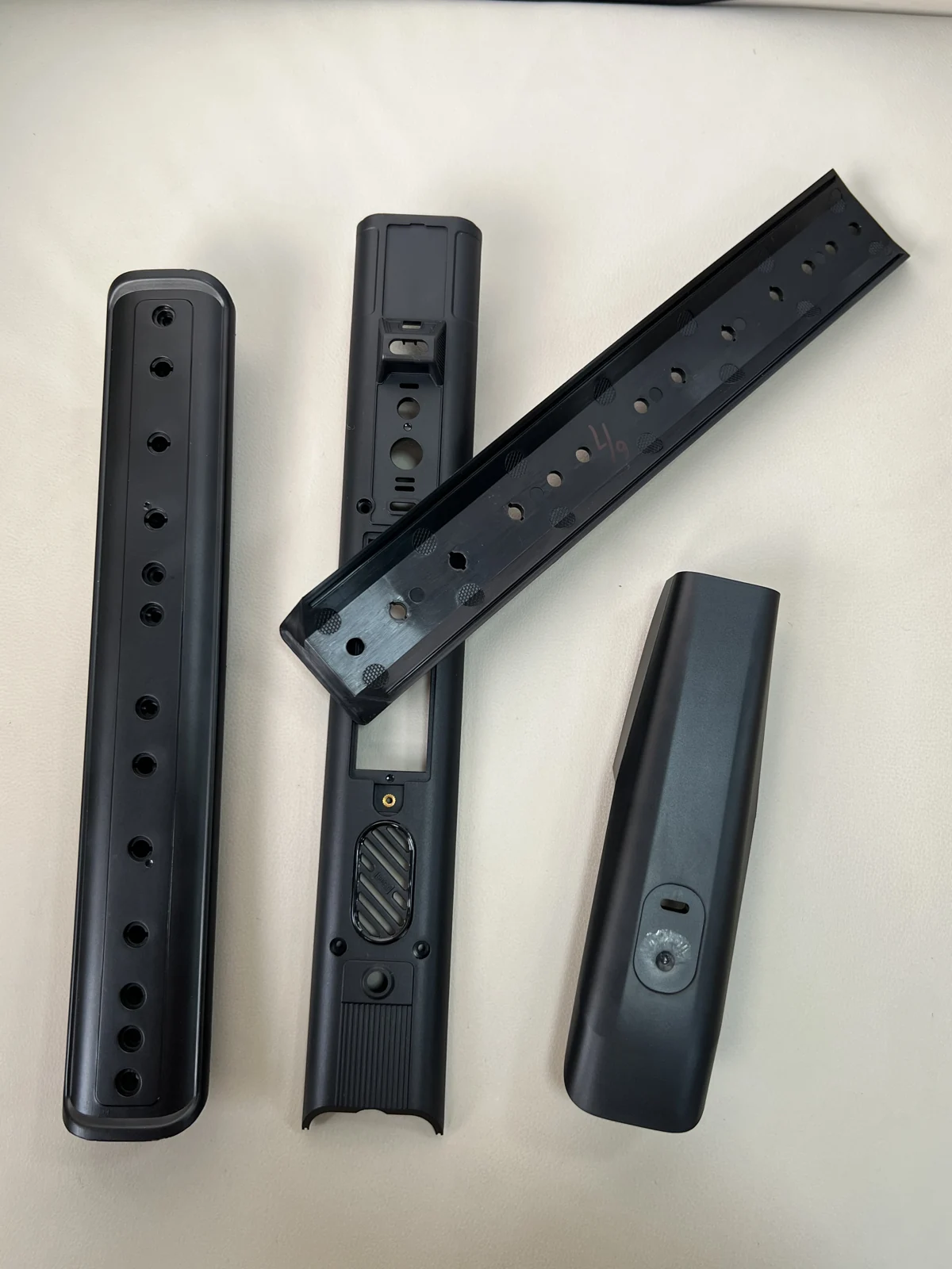
The narrower views reveal openings and local changes in section. These features can determine how the housing is supported and where a mating component is installed. They also deserve attention during a moulding review because the long flow path and different local sections should not be considered independently.
Autodesk’s design guidance identifies extensive thick regions as potential contributors to longer cooling and to sink or warpage concerns. For these sample geometries, that supports reviewing reinforcement, transitions and cooling layout before specifying a trial plan. It does not establish that any photographed part has a defect.
Approve fit at several locations
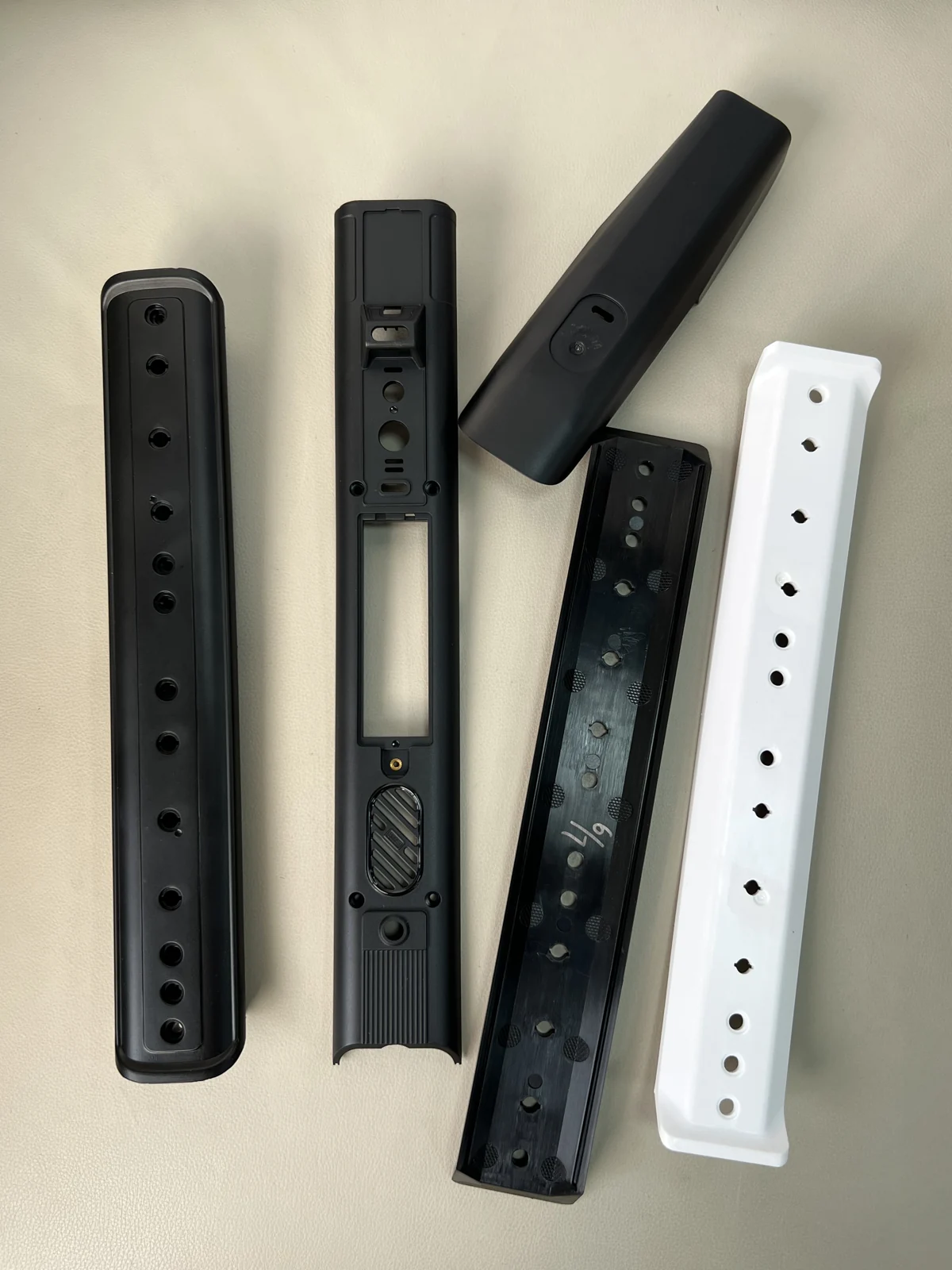
For a long cover, acceptable fit at one end does not necessarily prove acceptable fit along the entire edge. A practical trial review can check the first and last mounting positions, selected intermediate features and the relationship with the counterpart over its usable length.
Packing also matters for slender components. Parts should not be forced into a storage position that changes the geometry being inspected later. The appropriate support, stacking arrangement and inspection timing depend on the chosen resin and the assembly requirements, so these should be documented with the project rather than assumed from a sample photo.
Suggested sample approval checks
| Review area | What to agree before production |
|---|---|
| Overall profile | Define straightness against the intended inspection datum. |
| Hole positions | Check the relationship between mounting points along the length. |
| Mating edges | Confirm fit at both ends and selected intermediate positions. |
| Handling | Agree supports and packing that avoid unwanted loading. |
Planning a comparable part
Provide the complete housing and counterpart drawings, assembly sequence, cosmetic face requirements and the datums used for inspection. These inputs are more helpful than asking for a general tolerance across every feature of a long part.
Explore related moulded components →
Technical background: Manufacturer and moulding-design guidance. General guidance is not a test report for the photographed samples.
Discuss your part and assembly requirements
Share your 2D/3D drawings, material requirements and expected production volume for a project review.
Let’s Build Precision Moulds Together
Upload your CAD files or share your product specifications. Our engineering team will respond with a detailed quotation within 24 hours.