
 English
 Español
 Português
 Русский
 العربية
 Français
 Deutsch
 中文
中文 日本語
日本語 한국어
한국어Plastic Components That Integrate Metal Inserts
Sample-Based Manufacturing Review
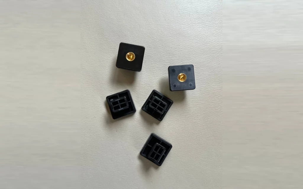
A small plastic component can perform several jobs at once when it is combined with a metal feature. JingZhan’s archive includes black moulded supports with visible metallic centres and a separate group of slim metal components. These samples provide concrete examples for discussing location, retention and accessible metal surfaces.
Identify what the metal feature is intended to do
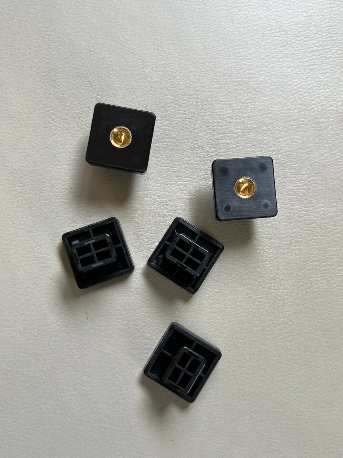
The first sample group shows similar outer shapes with different visible faces and central features. A review should establish whether the metal element is intended for fastening, locating, contact or another function. Appearance alone does not establish electrical rating, metal grade or the required joint strength.
The enquiry should therefore include the insert drawing, the plastic part drawing and the interface requirements. Exposed surfaces, orientation and the permitted position of the insert should be explicit. A general instruction to add a metal insert is not enough to define the acceptance criteria.
Choose the integration route from the actual design
A visible metal feature does not prove how a photographed sample was produced. Depending on the design, integration may involve insert moulding or an assembly operation after the plastic part is made. The chosen route must be reviewed against retention, access, thermal exposure and the required production sequence.
For insert moulding, locating and supporting the insert in the tool are important review topics. Autodesk’s insert-overmoulding guidance also notes that the polymer and metal can respond differently during cooling. This supports evaluating the combined geometry and process, rather than considering plastic shrinkage in isolation.
Protect exposed metal and verify the interface
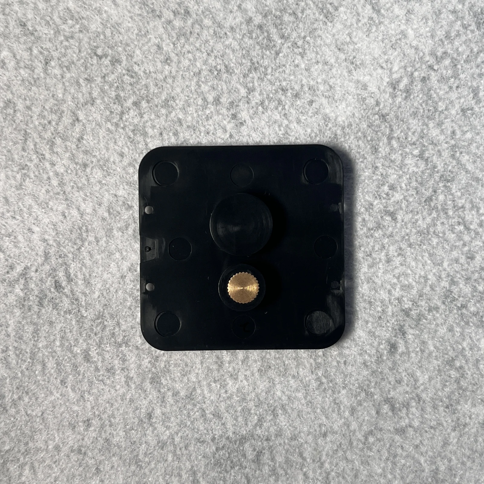
The slim metal components in the final photograph illustrate why exposed profiles and locating surfaces need separate specifications before they are combined with plastic. Those areas should be identified in the inspection and packing plan so they are not damaged, unintentionally covered or bent during handling.
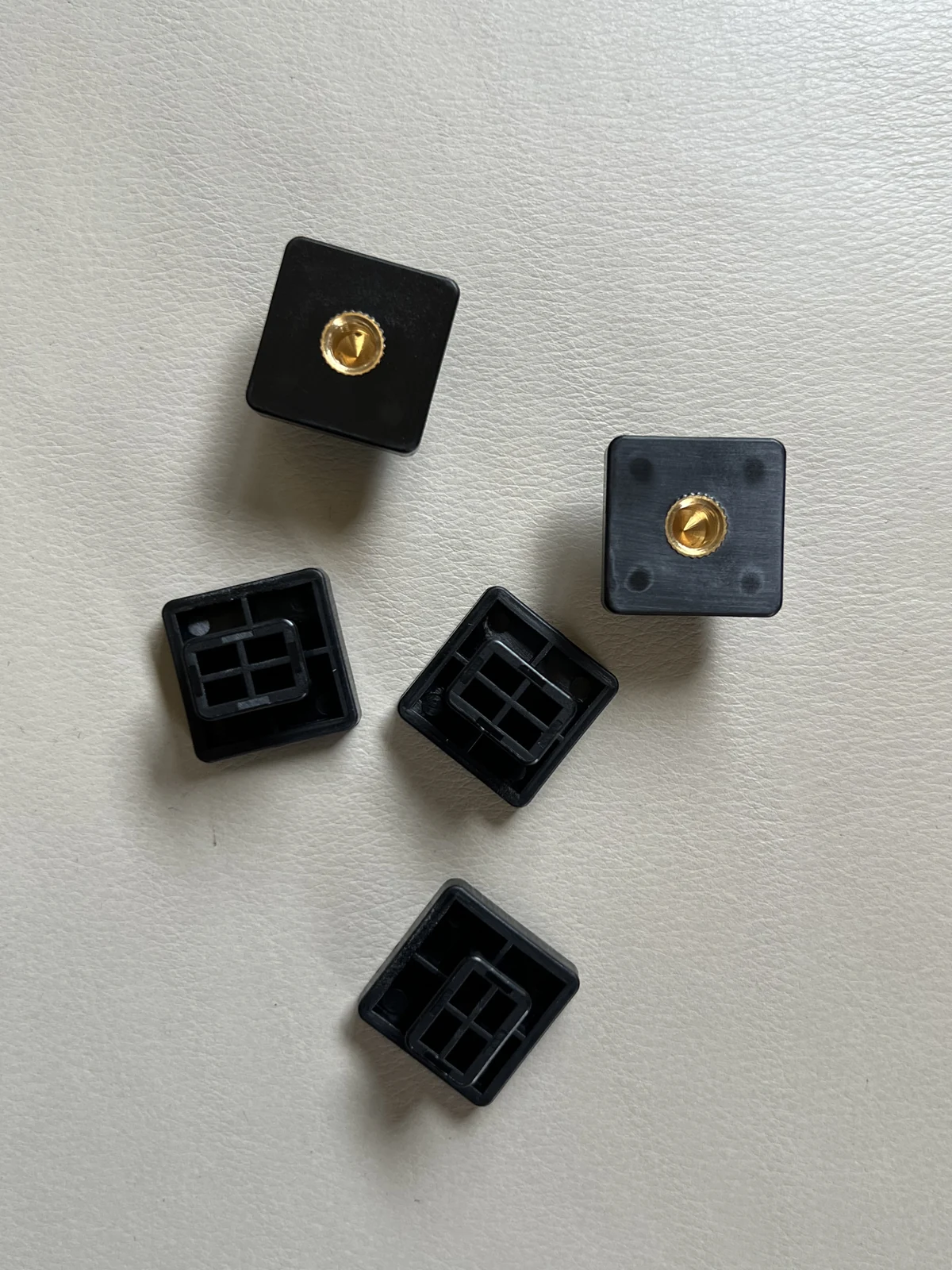
Sample approval can include insert position, visible plastic condition and fit with the counterpart. Pull-out, torque, electrical or other functional checks should only be claimed when they are required and supported by an agreed test. These photos illustrate the structures; they do not supply the resulting test values.
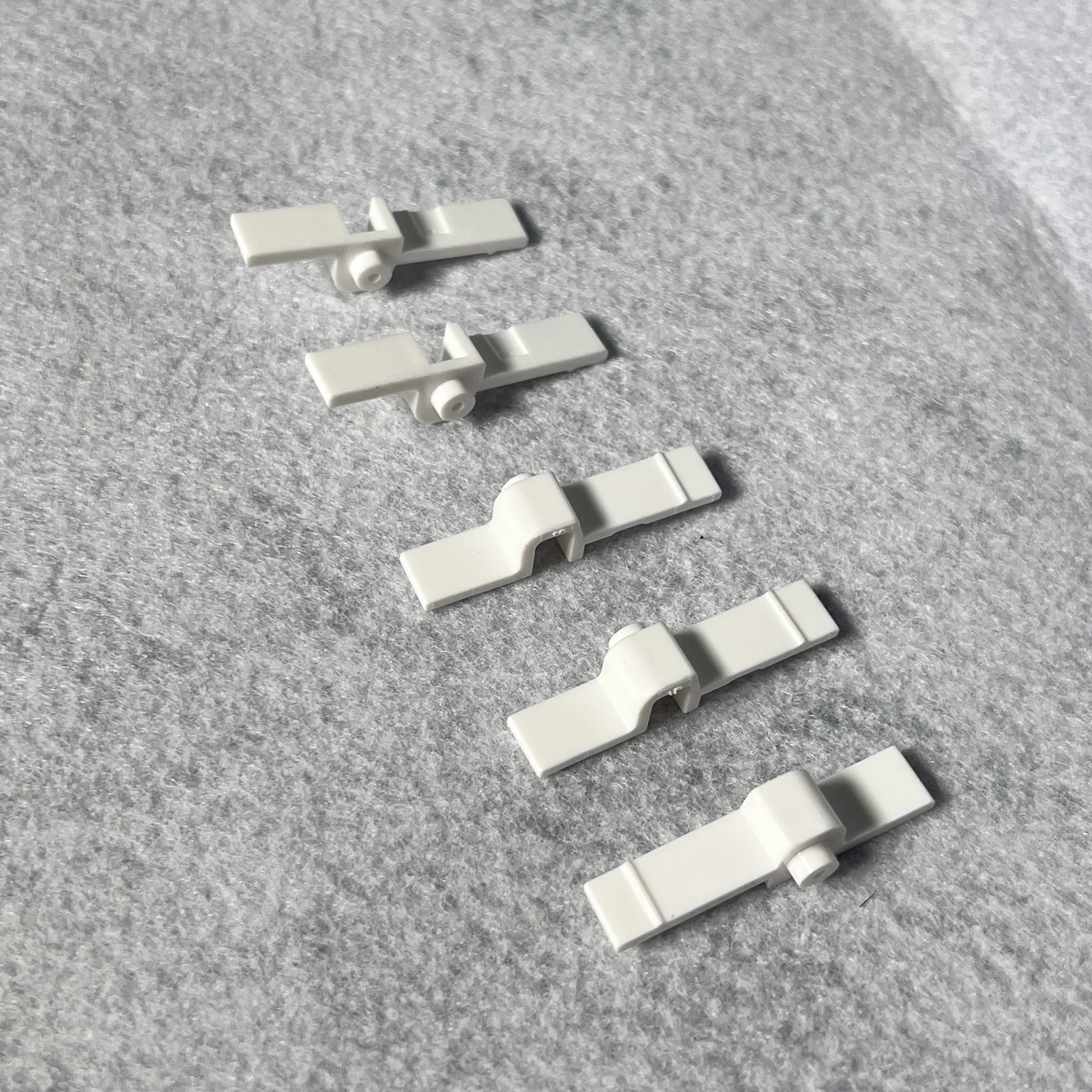
Suggested sample approval checks
| Review area | What to agree before production |
|---|---|
| Insert position | Agree location, orientation and permitted movement. |
| Exposed surfaces | Identify regions that must remain clear and undamaged. |
| Plastic interface | Review flash, local fill and the approved joint condition. |
| Retention or function | Use project-specific pull-out, torque or functional tests when required. |
Planning a comparable part
Send both component drawings, the metal specification, the intended integration route if already defined and the required verification method. If the route is open, the engineering review should resolve it before a production price or repeat-supply plan is finalised.
Explore related moulded components →
Technical background: Manufacturer and moulding-design guidance. General guidance is not a test report for the photographed samples.
Discuss your part and assembly requirements
Share your 2D/3D drawings, material requirements and expected production volume for a project review.
Let’s Build Precision Moulds Together
Upload your CAD files or share your product specifications. Our engineering team will respond with a detailed quotation within 24 hours.