
 English
 Español
 Português
 Русский
 العربية
 Français
 Deutsch
 中文
 日本語
 한국어
Ventilation Covers with Thin Ribs and Open Patterns
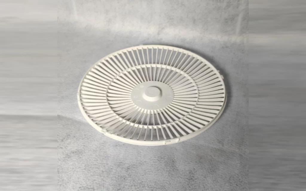
Sample-Based Manufacturing Review
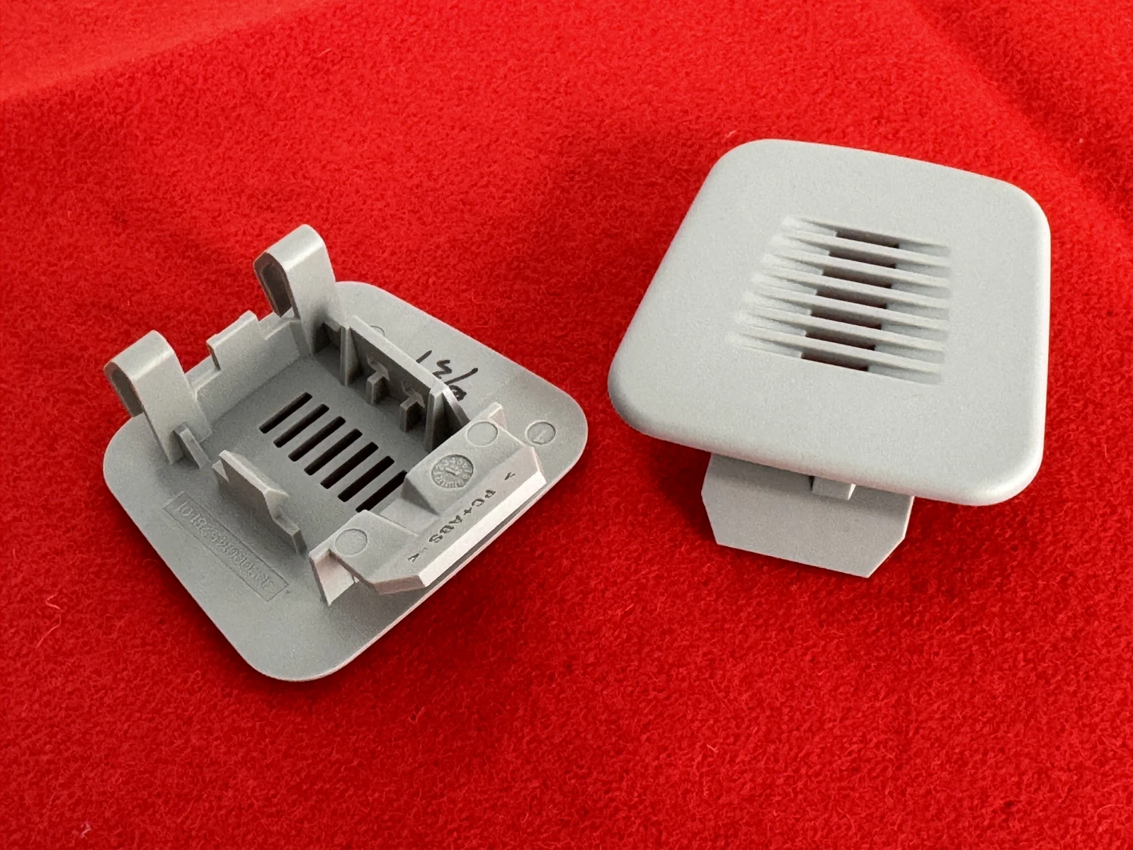
A ventilation cover must preserve an open pattern while still providing a usable mounting structure. The white samples in this archive include a circular radial grille, its reverse-side structure and smaller rectangular vented covers. Together they show why a part with many narrow openings needs more than an attractive front view to support manufacturing approval.
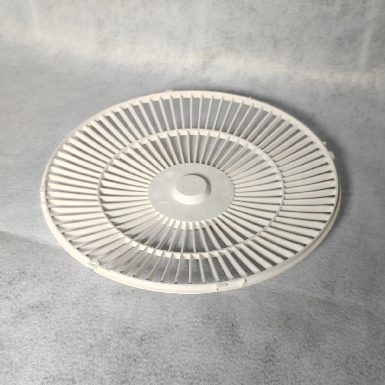
Read the pattern and the support structure together
The circular grille uses repeated ribs around a centre region. The angled photograph shows that the apparent two-dimensional pattern also has depth and a shaped perimeter. A review should identify which regions are open, which features are structural and how the cover attaches to its counterpart.
The required opening pattern should be defined on the drawing rather than estimated from a photo. If airflow, guarding or other functional performance is important, those requirements need their own design assessment and test conditions. A visually open grille does not establish an airflow value or a safety classification.
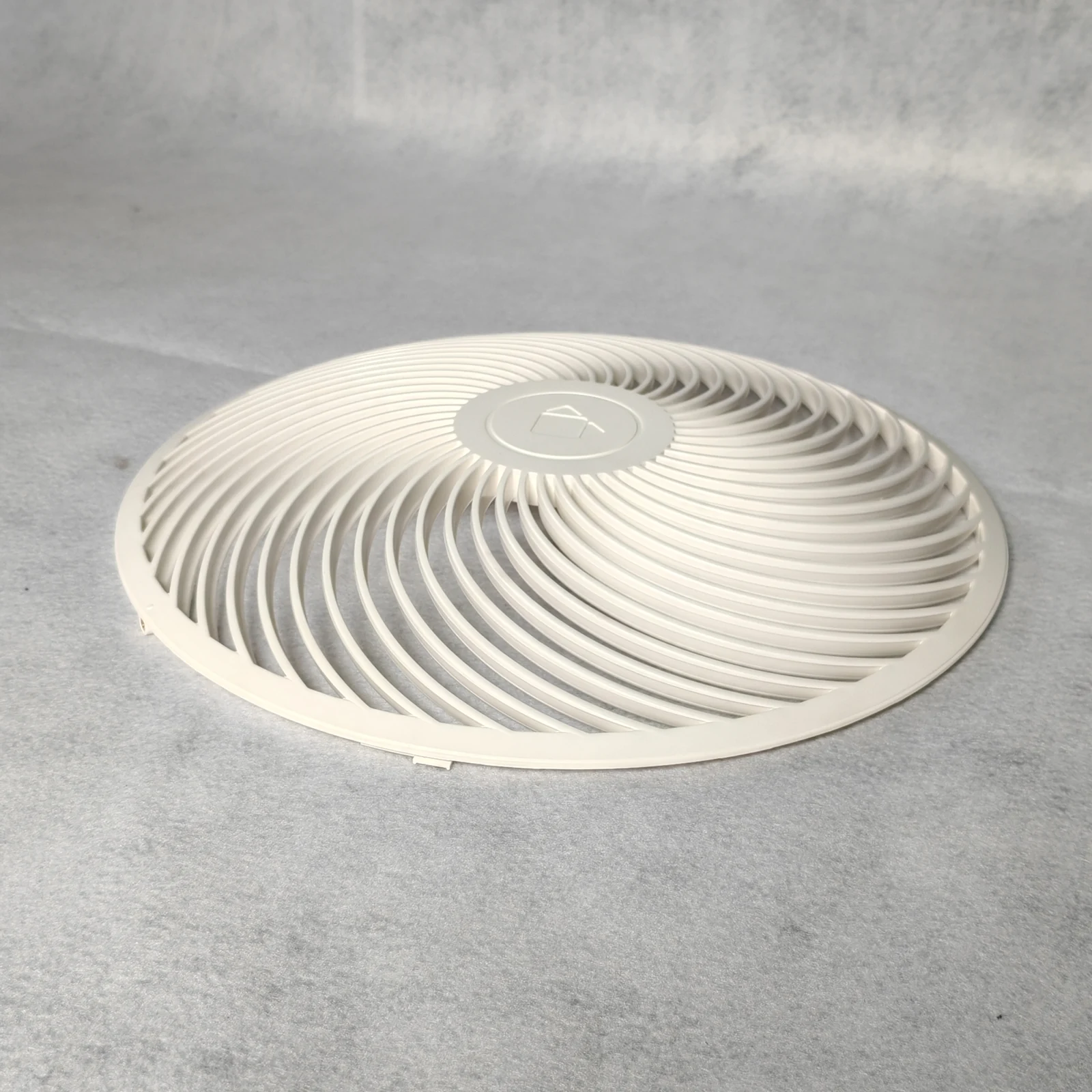
Review repeated thin features before tooling
The rib pattern creates many local features that need to fill and release consistently. During a DFM review, gate access, venting, release direction and support during ejection are useful subjects to examine. Delicate ribs and their intersections should be considered alongside the surrounding rim.
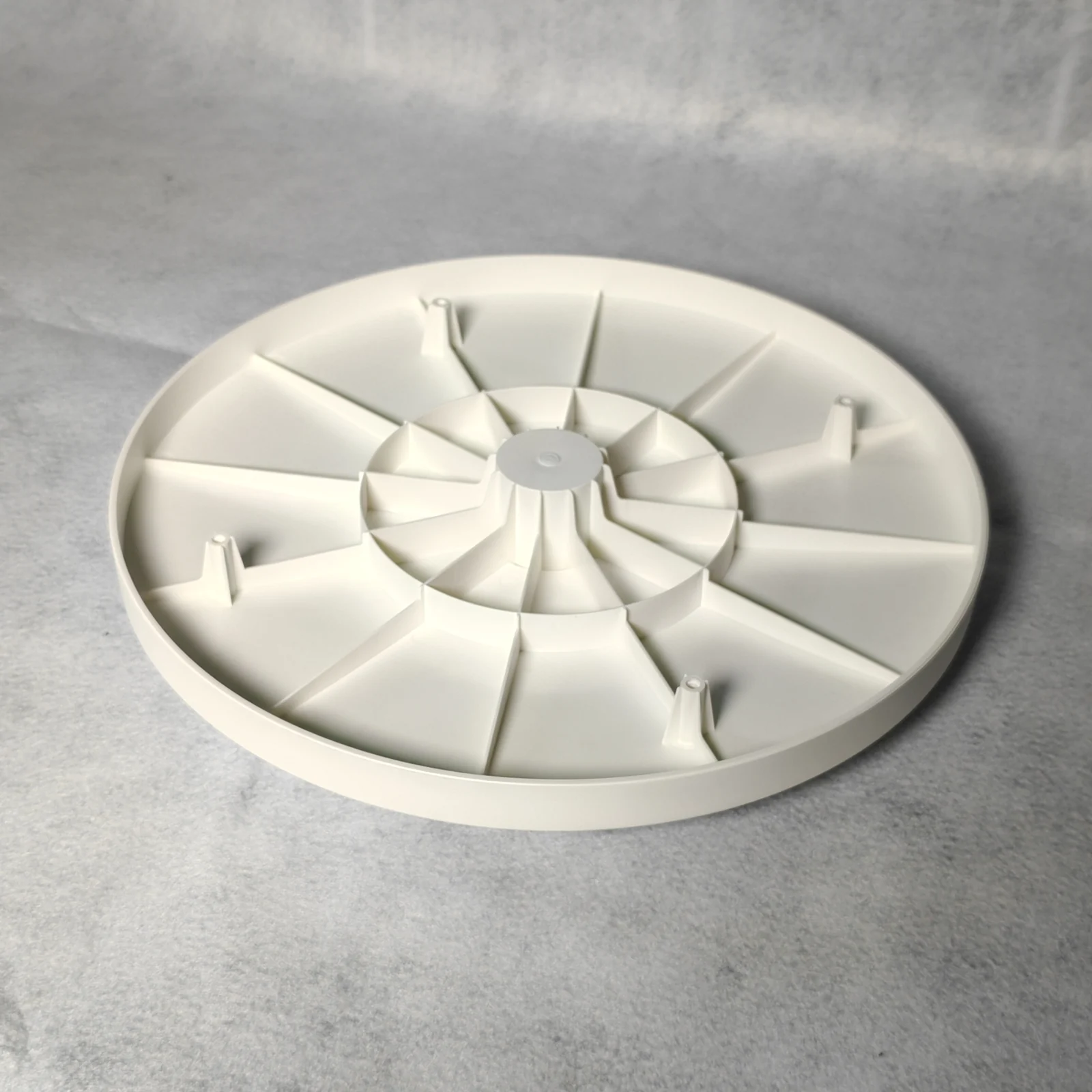
The reverse-side photograph shows where reinforcing geometry joins the main cover. Local section changes should be reviewed rather than assuming that additional thickness always improves a part. Material choice, the required appearance and the planned moulding process determine the appropriate detailed design.
Inspect openings as well as outside dimensions
The rectangular samples demonstrate that the same inspection principle applies to a different shape. An outside dimension can be correct while an individual slot is obstructed or a local rib is incomplete. The approval plan should therefore include the repeated pattern, not just the overall envelope.
A practical review can check visible flash in the openings, local damage, the perimeter profile and assembly fit. Any functional test should use the intended counterpart and defined conditions. Packing should also protect the raised pattern so that ribs are not loaded or distorted before installation.
Suggested sample approval checks
| Review area | What to agree before production |
|---|---|
| Open pattern | Check slot continuity and unwanted obstruction. |
| Ribs | Inspect incomplete features, flash and handling damage. |
| Perimeter | Review profile and fit against the counterpart. |
| Functional requirements | Validate airflow or guarding only against an agreed specification. |
Planning a comparable part
An effective enquiry includes the grille and counterpart drawings, material requirements, cosmetic face, mounting arrangement and any airflow or guarding criteria. This lets the tooling review focus on the repeated features that actually determine approval.
Explore related moulded components →
Technical background: Manufacturer and moulding-design guidance. General guidance is not a test report for the photographed samples.
Discuss your part and assembly requirements
Share your 2D/3D drawings, material requirements and expected production volume for a project review.
Let’s Build Precision Moulds Together
Upload your CAD files or share your product specifications. Our engineering team will respond with a detailed quotation within 24 hours.