
 English
 Español
 Português
 Русский
 العربية
 Français
 Deutsch
 中文
中文 日本語
日本語 한국어
한국어Ribbed Circular Covers Designed for Repeatable Assembly
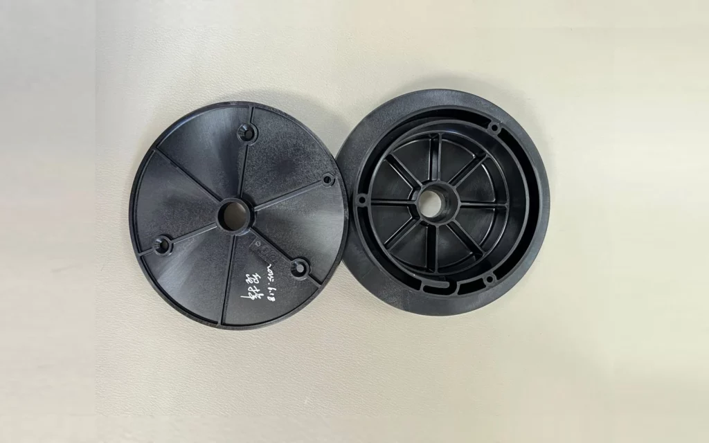
Sample-Based Manufacturing Review
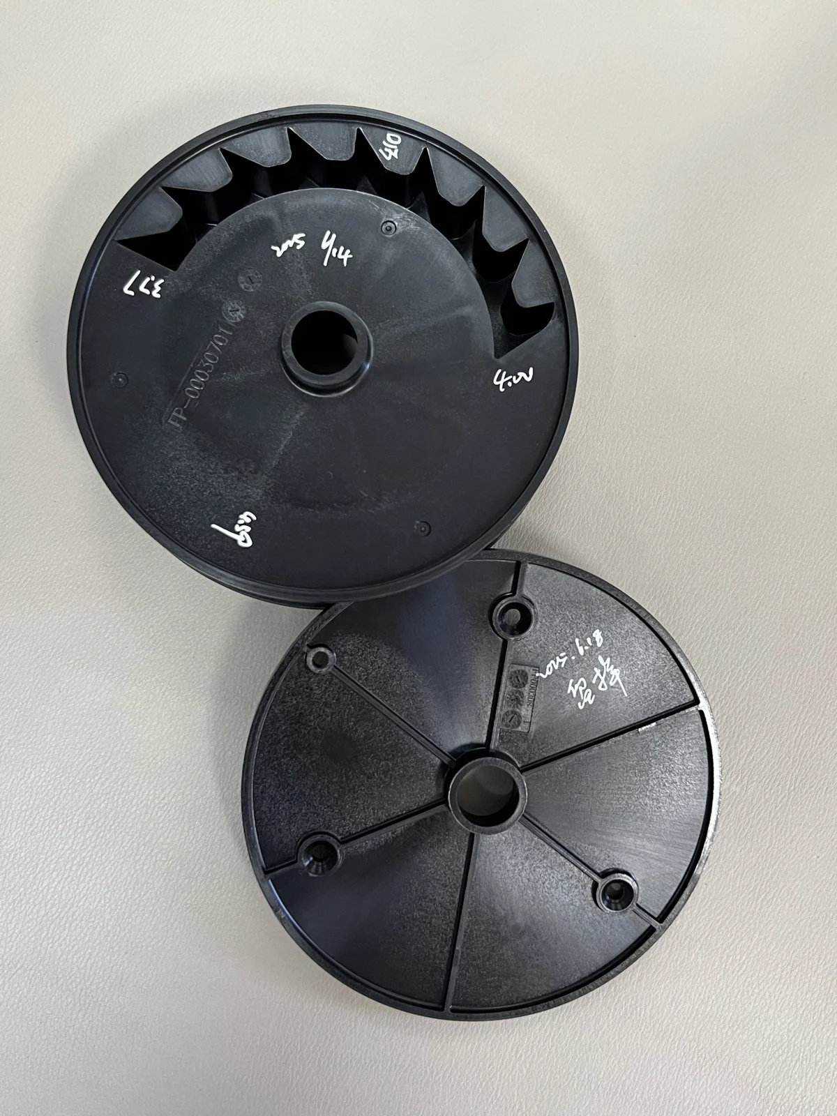
Circular covers can look uncomplicated from the outside while carrying a network of ribs and locating features on the reverse. These black moulded samples show radial reinforcement, central hubs and different perimeter details. The photographs are useful for examining how the front face, the internal structure and the mounting interface relate to one another.
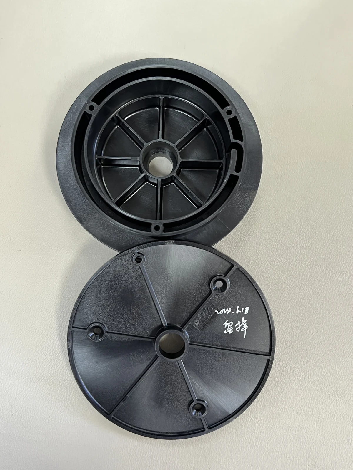
Separate the locating features from the visible face
One sample view exposes the reverse-side rib pattern; another shows the central feature and surrounding rim more directly. A manufacturing drawing should identify which diameter or face locates the part in the assembly. That choice establishes how the other features should be measured.
The central feature may locate another component, provide access or form part of a fastening arrangement. Its function cannot be determined from shape alone. Before tooling, the review should confirm the counterpart, intended clearance and whether the part is stationary or has any movement in service.
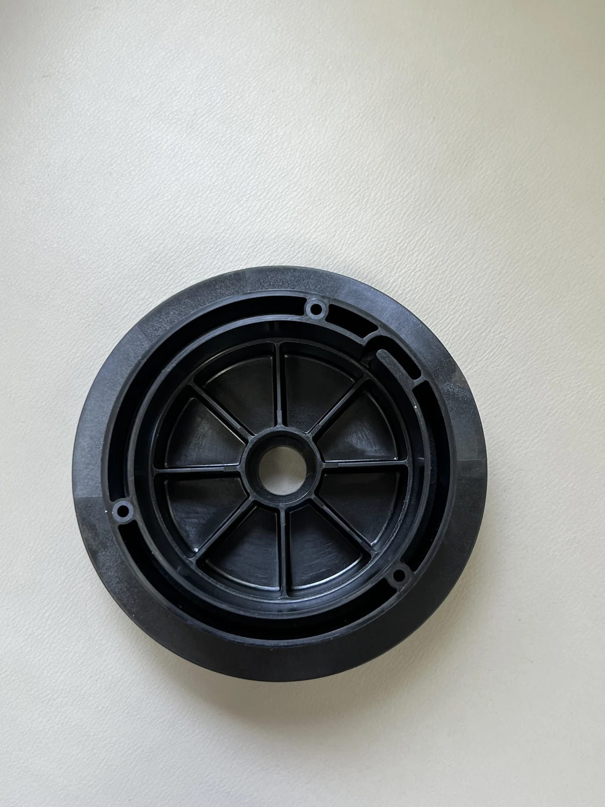
Treat the rib junctions as part of the moulding review
The radial ribs connect the perimeter to the central area. A review should consider their junctions and transitions alongside the nominal wall rather than simply adding more material wherever stiffness is desired. Thick local intersections deserve particular attention when appearance on the opposite face matters.
The purpose of this review is to balance geometry, release and the required assembly fit. It is not a claim that all circular parts need the same rib dimensions or the same gate layout. The selected resin, overall size and required face quality should inform those decisions for the actual project.
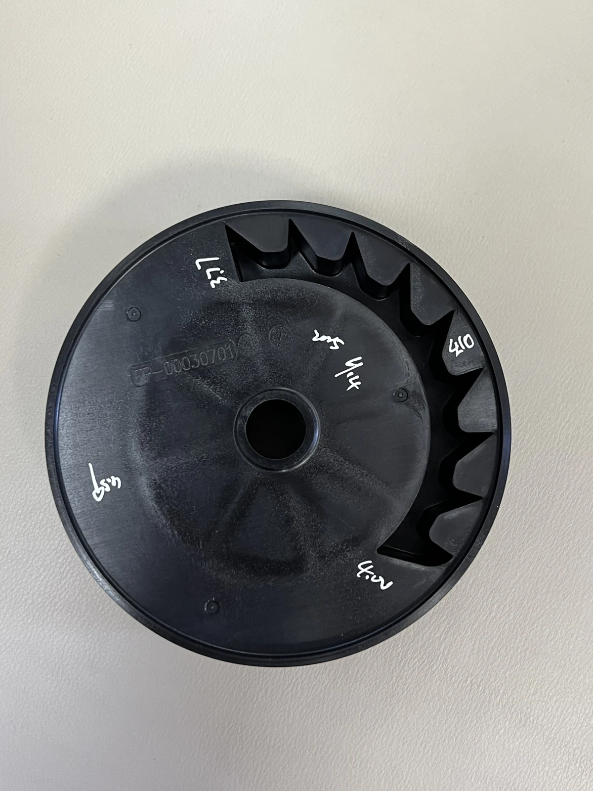
Check the complete circular interface
A diameter measurement alone may not describe the condition that matters during assembly. Depending on the design, inspection may need to consider face flatness, the relationship of the hub to the rim, and the engagement of tabs or other perimeter features.
The paired samples also show why front and reverse views belong in a sample approval record. They let the buyer identify which surfaces are cosmetic and which must remain free of interference. If the part is intended to rotate, runout and functional movement require a separate agreed check; no rotational performance is established by the photos.
Suggested sample approval checks
| Review area | What to agree before production |
|---|---|
| Locating diameter | Measure from the datum defined for the assembly. |
| Hub relationship | Check position and clearance against the counterpart. |
| Face and rim | Review flatness or profile where the design requires it. |
| Perimeter details | Confirm engagement and absence of unintended interference. |
Planning a comparable part
For a comparable component, supply both-side drawings, the locating scheme and a description of the assembled function. Mark the critical face and identify any rotational, fastening or cosmetic requirements so they can be addressed in the tooling and inspection plan.
Explore related moulded components →
Technical background: Manufacturer and moulding-design guidance. General guidance is not a test report for the photographed samples.
Discuss your part and assembly requirements
Share your 2D/3D drawings, material requirements and expected production volume for a project review.
Let’s Build Precision Moulds Together
Upload your CAD files or share your product specifications. Our engineering team will respond with a detailed quotation within 24 hours.