English
 Español
 Português
 Русский
 العربية
 Français
 Deutsch
 中文
 日本語
 한국어


Industrial Electronic Equipment Housings
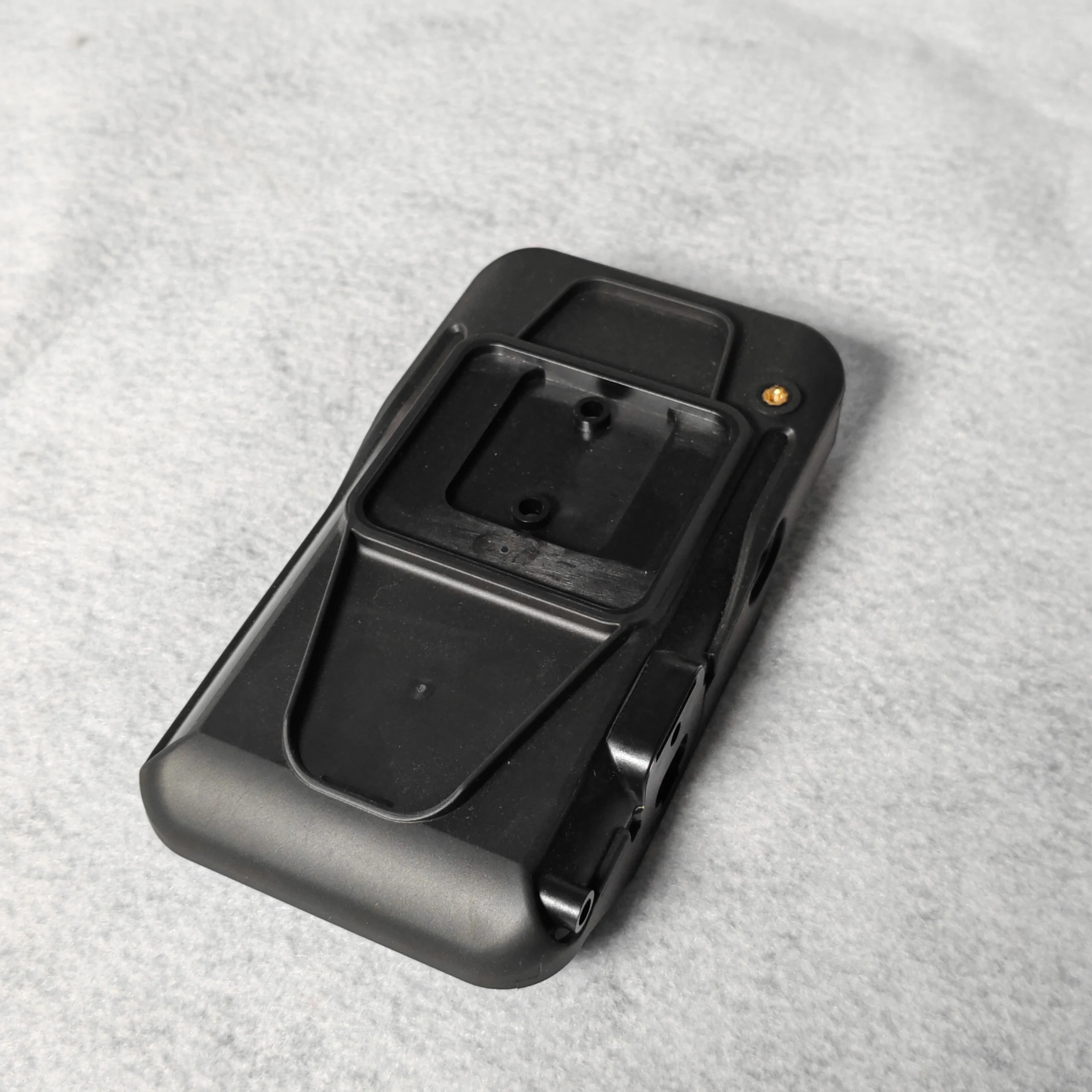
These industrial electronic equipment housings are engineered for industrial controllers, power electronics and protected machine-side devices, from early DFM review through repeat production. The molding plan is developed around robust wall and rib structures, organized cable-entry and connector interfaces, and serviceable covers with stable sealing geometry. Resin selection, gate location, parting lines and inspection points are matched to the mating parts, operating environment and expected production volume.
Product Overview
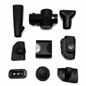
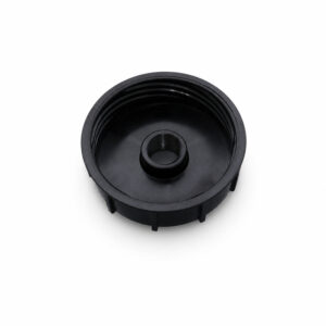
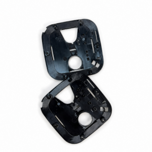
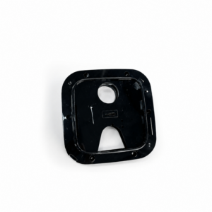
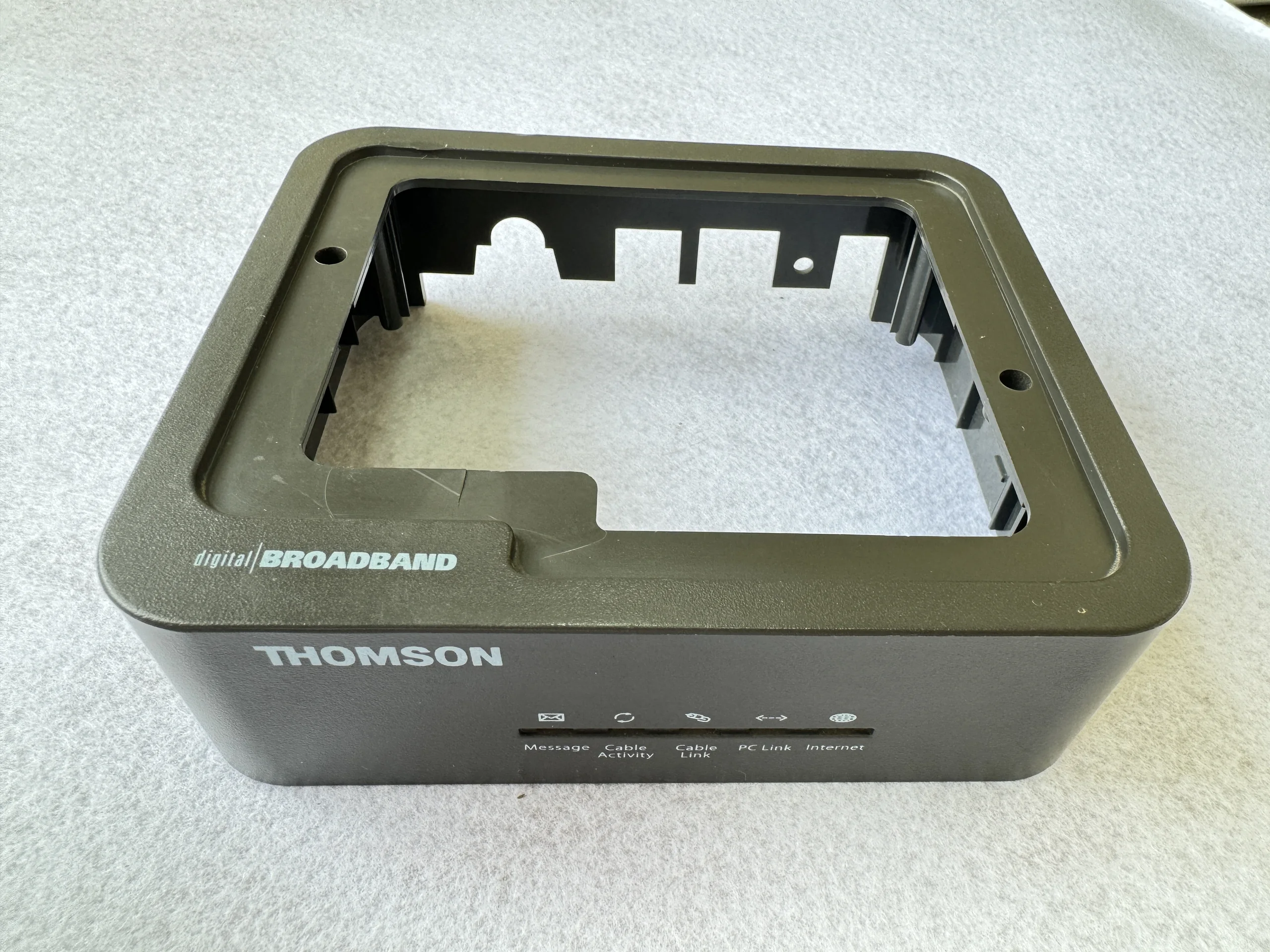
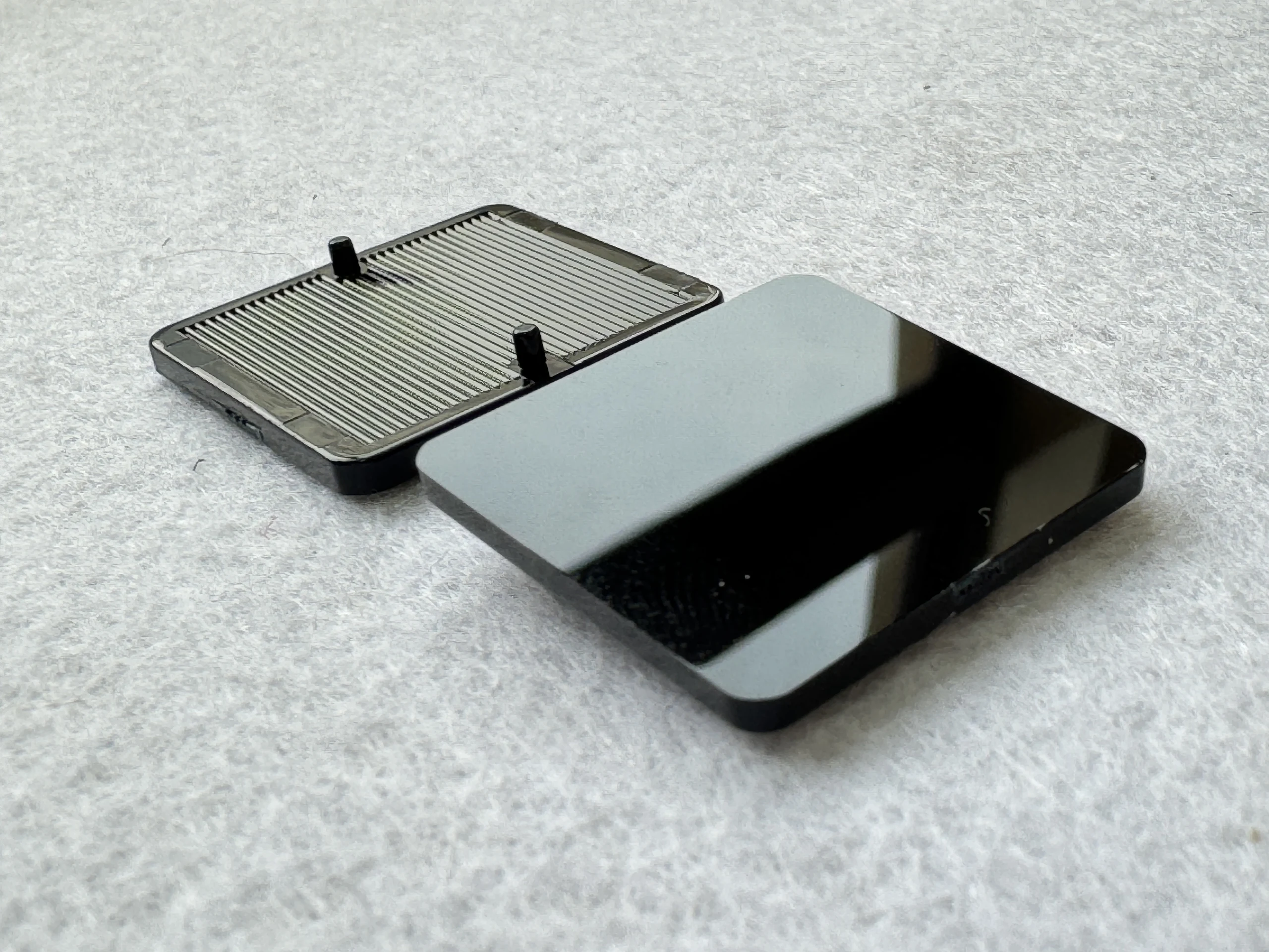
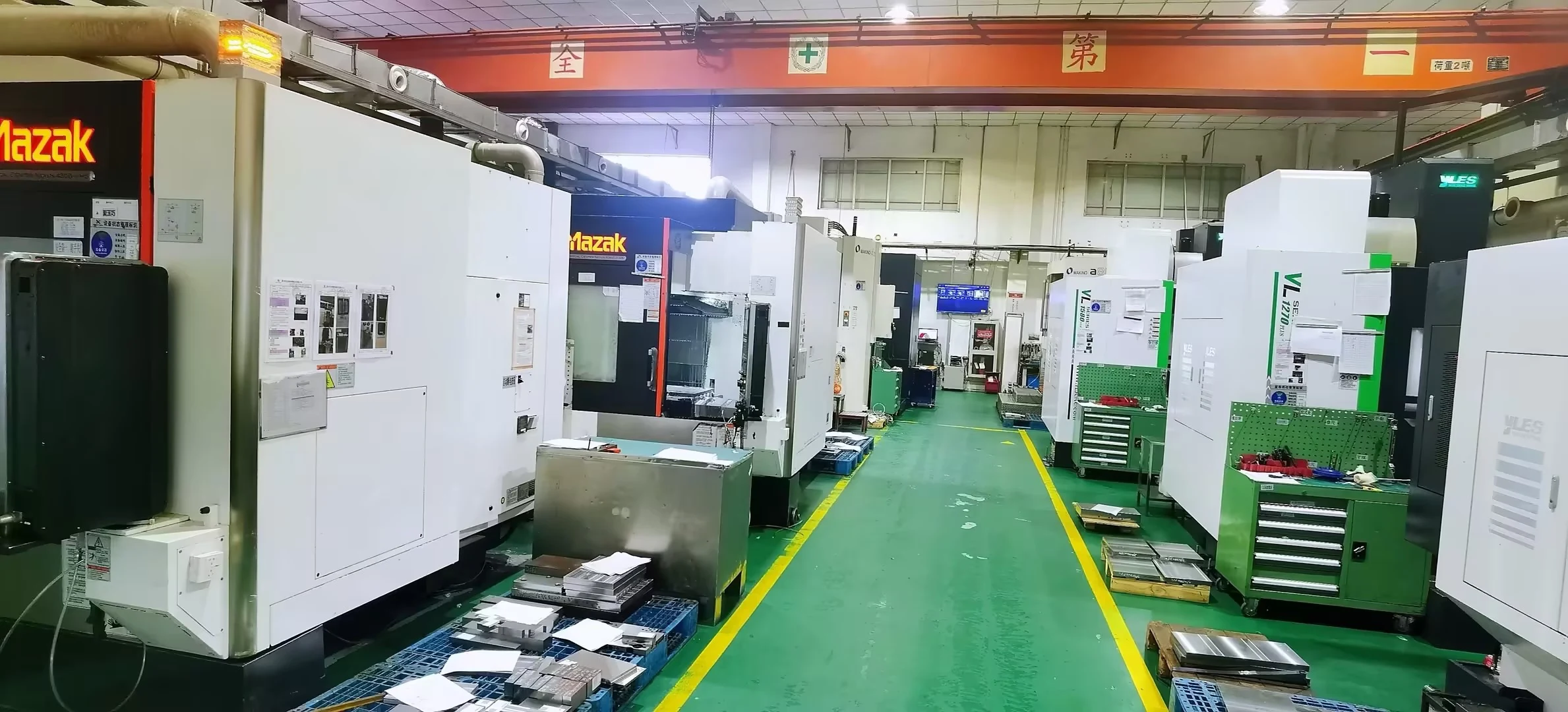
Industrial electronic housings bring together operating openings, mounting geometry and service access. JingZhan supports dedicated tooling and component moulding against the customer’s equipment brief. Environmental or electrical protection is validated for the complete design, not inferred from the enclosure shape. DESIGN AND MANUFACTURING Define temperature, chemicals, installation and handling exposure. Specify any grade or test requirements with acceptance criteria before material and tool decisions are finalised. Check board supports, connector openings and service clearances together. Confirm how the housing is fixed and opened so moulded details do not block installation or maintenance. Agree any sealing, impact, thermal or electrical tests separately. Surface finish and a closed-looking shell do not establish an IP, flame or EMC rating. TECHNICAL SPECIFICATIONS PRODUCTION AND REPEAT SUPPLY The supplied company equipment inventory includes 50–500-tonne moulding machines, CNC and EDM tooling resources, plus CMM and optical measurement equipment. Press selection depends on shot volume, projected area, resin and cavity layout. Equipment capability does not establish one tolerance for every moulded feature. Repeat supply should follow the approved drawing, resin grade, reference samples and inspection plan. Agree material-lot identification, cavity tracking where required, packaging and change approval. Plan tool maintenance and releases around actual demand so later batches remain comparable to the approved baseline. Tooling investment is quoted separately from the piece price. Share annual demand and release quantities so cavity count, procurement and batch cost can be reviewed together. RELATED APPLICATIONS Industrial controllers and instrumentation enclosures. Custom handheld or panel-mounted electronic equipment housings. Photographs show company-manufactured component examples, not standard products with shared specifications. Electrical, flame, optical, environmental or other performance claims require grade documentation and project-specific validation. Discuss your drawing and supply requirements. Send CAD, resin preference, critical features, annual demand and release quantity. Contact our engineering team →Industrial equipment housings with coordinated access and protection
Key processing requirements
Start from the service environment
Coordinate assembly and access
Scope functional validation
Parameters agreed for your part
Parameter
Project specification
Manufacturing scope
Custom mould tooling, injection moulding and trial approval.
Material selection
PC/ABS, ABS, PC or an engineering grade selected against service conditions.
Engineering focus
Operating windows, connector access, mounting interfaces and cover joints.
Dimensions and tolerance
Approved drawing; feature-specific agreement and inspection method.
Colour and finish
Grade, colour, texture and cosmetic zones confirmed before trials.
Tool arrangement
Cavity count and inserts selected against geometry and demand.
Quality records
First-article and agreed batch checks; reporting scope quoted.
Delivery
Protected parts or agreed sets with lot and revision identification.
Equipment, lead time and order planning
Planning item
Basis for quotation
DFM review
Indicative 3–5 working days after complete drawings and requirements.
New tooling
Indicative 4–8 weeks to first tool trial after tool-design approval and commercial release; corrections and customer validation are additional.
Order quantities
Initial quotation-planning basis: a 500-piece pilot or 1,000-piece repeat batch per part number, resin and colour, subject to project quotation.
Repeat orders
Indicative 10–15 working days after materials and the production slot are confirmed. Customer qualification, special processing and transit are additional.
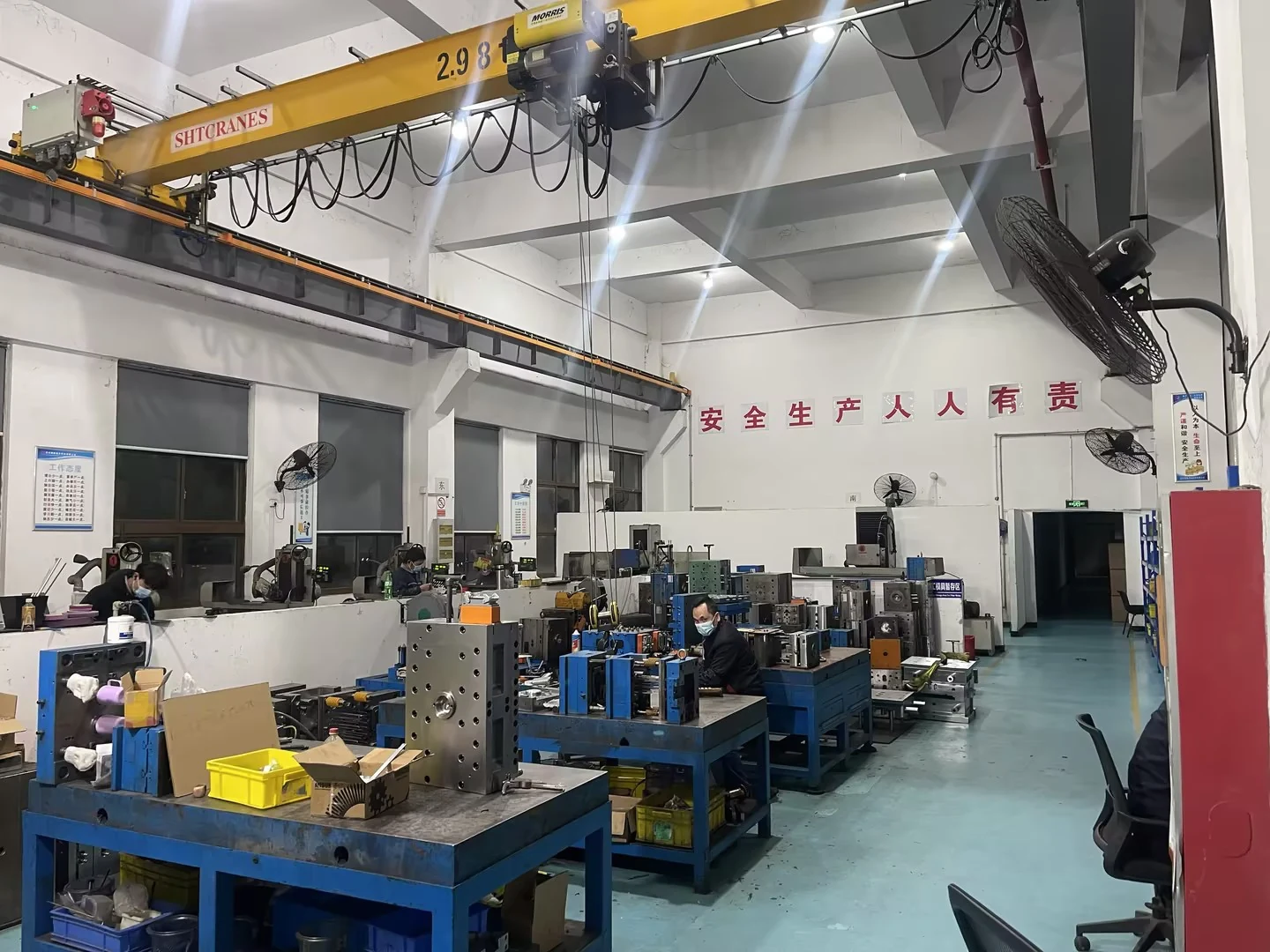
Keep repeat orders on an approved baseline
Where these components can be used
Technical Specifications
| Process | Custom precision plastic injection molding |
|---|---|
| Product Group | Industrial Electronic Equipment Housings |
| Typical Applications | industrial controllers, power electronics and protected machine-side devices |
| Material Options | ABS, PC/ABS, PC, PA, POM, PMMA and other engineering resins selected for function and appearance |
| Engineering Focus | robust wall and rib structures, organized cable-entry and connector interfaces, and serviceable covers with stable sealing geometry |
| Project Support | DFM review, mold design, mold trials, assembly validation and repeat production |
| Customization | Geometry, color, texture, resin, inserts and packaging can be developed to project requirements |
Recommended Products
Explore our high-precision injection moulded components trusted by industry leaders worldwide.